Cable carrier inner width: the 60% fill rule
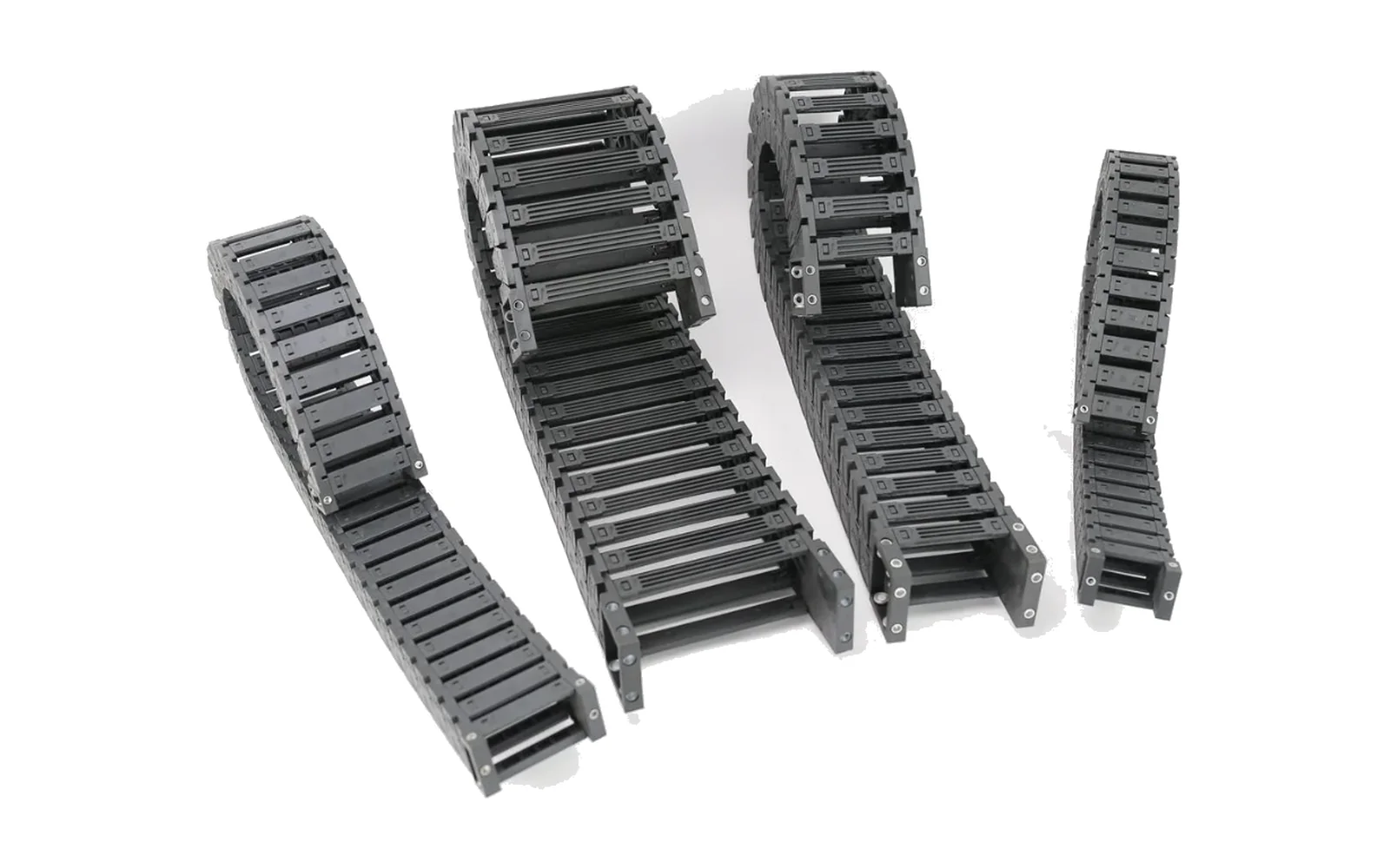
Too narrow and cables chafe; too wide and you overspend. Three steps: total cable cross-section from outer diameters, the 60% fill ceiling, then the width step.
"Just quote the next width up, the difference is pennies" — I have seen that line on quotation sheets far too many times. Every step up in inner width enlarges the links, side plates and pins with it, so the cost genuinely climbs. Quote too narrow, and the cables chafe against each other inside the cavity; three months later the customer comes back for a replacement chain.
Inner width is not something you pick by eye. It is an arithmetic problem. This article breaks it into three steps you can work through with a calculator and a cable outer-diameter table.
The conclusion first: three steps to an inner width
- Total cross-section — take every cable and air hose in the cavity, compute its circular area from the outer diameter, and add them up
- Divide by the fill rate — total cross-section ÷ 60% gives the minimum cavity area required
- Convert to inner width — divide that area by the inner height you intend to use, then round up to the next standard width
The order cannot be rearranged. Skipping step one and going straight to the catalogue table is the most common mistake.
Step 1: get the total cable cross-section right
Per cable, use the outer diameter — not the conductor cross-section
This is the first trap. Cable datasheets often read "4×1.5 mm²", but that is the conductor cross-section, not the space the cable occupies.
What occupies space is the outer diameter:
- A cable with a nominal outer diameter of 8 mm occupies π × 4² ≈ 50.3 mm²
- Its conductor cross-section may be only 4×1.5 = 6 mm²
That is a factor of more than eight. Size the inner width from conductor cross-sections and the result is absurdly small — the cables will not physically fit.
Get outer diameters from the cable supplier, or measure them with a calliper. On multi-core flexible cables the outer diameter depends on the lay length and sheath thickness; the same nominal size can differ by 1–2 mm between manufacturers. Use the data for the exact cable you will buy, not a generic figure from a catalogue.
Add a bundling factor for multiple cables
Cables lying side by side in a cavity are not a dense packing of tangent circles. Bundling, bending and differing routing leave gaps, and the edges of the cavity go unused.
The usual practice is to allow 10%–20% layout margin, that is a bundling factor of 1.1–1.2. Take the upper figure for highly flexible cables, screened cables, and power and signal cables that must be run in separate compartments.
Therefore:
Total cross-section = Σ (circular area of each cable) × bundling factor
If the cavity also carries air, oil or fibre-optic lines, add their areas by outer diameter as well. Fibre optics need their minimum bend radius checked separately — that limit is usually stricter than for cables.
Step 2: 60% is a ceiling, not a target
The ceiling generally used in the industry is 60% — the total cable cross-section should not exceed 60% of the carrier's internal cavity area.
Why must that remaining 40% be left free? Three reasons:
- Cables must be able to move inside the cavity. The carrier reciprocates between straight and curved sections, so the relative position of every cable keeps changing. Fill the cavity and there is no room to move; cables are repeatedly stretched and pinched.
- The curved section offers less usable space than the straight one. When links rotate, the effective cavity contracts. Run at full fill and the cables press against the side plates through the bend.
- Heat dissipation. Cables packed tightly together cannot shed heat, and the sheath ages faster.
So 60% is a ceiling, not a recommendation. Reduce it in these cases:
| Duty | Recommended fill |
|---|---|
| Conventional horizontal reciprocation | ≤ 60% |
| High-speed reciprocation | ≤ 50% |
| Power and signal cables mixed | ≤ 50%, in separate compartments |
| Long stroke, unsupported | ≤ 50% |
| Air or oil lines sharing the cavity | ≤ 50% |
One clarification: the fill rate is an industry rule of thumb, not a product specification. The final figure should come from the supplier's calculation against your actual cable list.
Step 3: convert the area into an inner width
Cavity area = inner width × inner height, so:
Minimum inner width = total cable cross-section ÷ 60% ÷ inner height
An example. A small CNC machine needs 4 power cables (outer diameter 8 mm), 6 signal cables (5 mm) and 2 air hoses (6 mm) in the cavity.
Total cross-section first:
- Power cables: π × 4² × 4 = 201 mm²
- Signal cables: π × 2.5² × 6 = 118 mm²
- Air hoses: π × 3² × 2 = 57 mm²
- Sum 376 mm²; with a bundling factor of 1.15, about 432 mm²
Divide by the fill rate: 432 ÷ 0.6 ≈ 720 mm² of minimum cavity area.
Choose a medium series with a 25 mm inner height: 720 ÷ 25 ≈ 28.8 mm, so the minimum inner width is roughly 29 mm. The 25 series starts at a 25 mm inner width and steps upward, so take the first step not smaller than 29 mm (see the series dimension table for the actual steps).
The critical point here is round up to the next step, not round to nearest. The direction of rounding is always upward.
Inner width coverage of the main series
| Series | Inner height | Standard inner width range | Available bend radii |
|---|---|---|---|
| Micro 5 | 5mm | 5–7mm | R10 / R15 |
| Micro 6 | 6mm | 10mm | R18 |
| Micro 7 | 7mm | 7–10mm | R15 |
| Micro 10 | 10mm | 6–40mm | R18 / R28 / R38 |
| Micro 15 | 15mm | 15–50mm | R28 / R38 / R48 |
| Medium 18 | 18mm | 18–50mm | R28 / R38 / R48 / R55 / R60 / R75 / R100 |
| Medium 20 | 20mm | 25–103mm | R55 / R75 / R100 / R125 |
| Medium 25 | 25mm | 25–103mm | R40 / R48 / R55 / R75 / R100 / R125 / R150 / R175 / R200 / R250 |
| Medium 30 | 30mm | 25–103mm | R55 / R75 / R100 / R125 / R150 |
| Heavy 45 | 45mm | 50–300mm | R75 / R100 / R125 / R150 / R175 / R200 / R250 / R300 |
All figures are standard steps; non-standard inner widths require separate confirmation of tooling and lead time. Every series is glass-fibre reinforced nylon with a nominal operating temperature of -20 °C to 120 °C. Full dimension tables are on the medium cable carrier series page and the micro cable carrier series page.
The four most common mistakes
1. Using conductor cross-section instead of outer diameter. As above, the difference runs to several times over. This is the number one error and the biggest cause of quotation rework.
2. Calculating at the 60% ceiling. 60% is the upper limit. A width derived at the ceiling has no margin, and assembly reveals that the cables simply will not lay out. For conventional duty, aim for 45%–55%.
3. Forgetting the curved section. Size the width from the straight-section layout and the cables will press the side plates in the bend. The smaller the bend radius R, the more the cavity contracts through the bend; allow extra there separately.
4. Mixing cables and hoses into one total without compartmentalising. Put power and signal cables in the same compartment and the electromagnetic interference from the power cables couples into the signal lines. That is not a selection problem but a structural one — either choose a cross-bar type with separators, or keep two widths of margin and run them apart.
Incidentally, when several cables are run tightly bundled the current-carrying capacity must be derated. The reduction factors for groups of cables can be referenced to IEC 60287-2-2 (calculation of the current rating — a method for calculating reduction factors for groups of cables in free air). Where heat dissipation is constrained, this belongs in the calculation alongside the fill rate.
When to jump a step up
In three situations, stop agonising over the current step and go one size up:
- The cable list is not final and more cables are likely to be added
- Expansion margin is explicitly wanted, for example sensors or vision added later
- The bend radius is set very small, with R already near the series minimum
The extra cost of one step up is usually far below the cost of a rework because the cables would not fit.
Data to prepare before ordering
Send all four at once and you save days of back-and-forth:
- Cable list — the outer diameter and quantity of each, marked as power, signal, air hose or fibre
- Minimum bend radius of each cable — ask the cable supplier for written data rather than estimating
- Mounting — horizontal or vertical, unsupported or in a guide channel, and stroke length
- Operating data — speed and acceleration, or simply cycle time and stroke to derive them
If the cable list is still a draft, send it anyway. We will compute a version against the worst case, and you can fine-tune once the list is final. That is far quicker than waiting for a frozen list before starting.
On bend radii, you can ask your cable supplier for the test-method statement covering flexibility and mechanical properties, usually following the IEC 60811 series (test methods for insulating and sheathing materials of electric cables). For the machine side, cable routing and bending requirements can be checked against IEC 60204-1 (safety of machinery — electrical equipment of machines), which sets out the principles for routing flexible cables at moving parts. Both are references at the level of method and requirement; the actual figures still come from your cable supplier's measured data.
Frequently asked questions
Can I simply widen the inner width myself?
A cable carrier is a modular product, and on most bridge-type series the inner width is set by the cross-bar length. Some series can be built to non-standard inner widths beyond the standard steps, but tooling and lead time must be confirmed — it is not a matter of cutting a bar shorter.
Is a wider inner width always safer?
Safer to assemble, more expensive to buy. Widening the inner width enlarges the links, side plates and pins along with it; load capacity does not rise for free, while weight, centre of gravity and cost all go up. The principle is "one step of margin beyond what is sufficient", not "wider is better".
Can cables and hoses share one compartment?
They can, with sufficient margin — but power and signal cables are best run in separate compartments.
Can we visit the factory?
Welcome. The manufacturing entity is in Yueqing, Zhejiang (Tiancheng Street), where factory audits and sampling are arranged and the lines and tooling can be seen in person; production runs under an IATF16949 system. Changzhou is our permanent sales office for day-to-day contact, not a factory.
Can you do the calculation for us?
Yes. Send the cable list (outer diameter plus quantity) and we will produce a recommended inner width and bend radius for your actual configuration. On request we can also supply 3D drawings so the space can be laid out at the design stage.
Closing
Sizing an inner width is ultimately arithmetic: total cross-section → divide by fill rate → divide by inner height → round up one step. Cut any of the four corners and the assembly floor will hand the bill back to you.
If you are unsure, send us the list and we will run the numbers on your real cables. The selection process is set out in the five-step guide, full dimension tables are in the download centre, or contact us with your parameters directly.