Cable carrier bend radius: R and cable OD
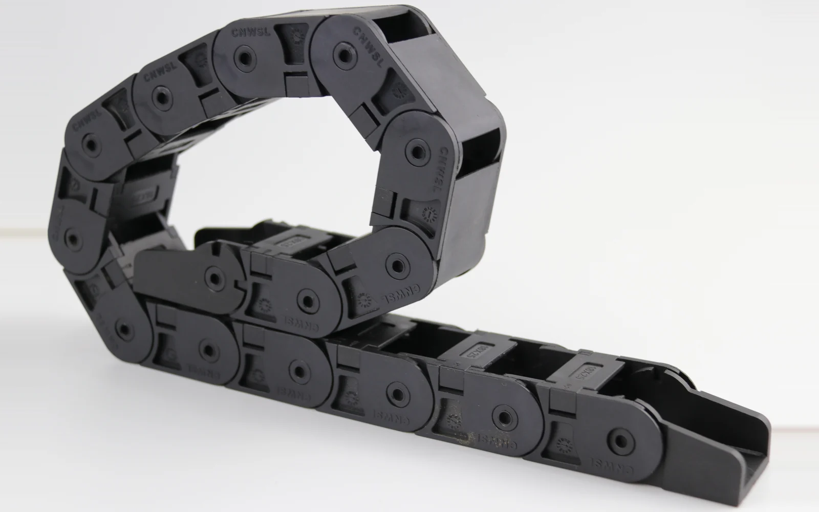
Cable diameter, duty and travel set the bend radius R. Here is the R-to-cable-OD factor rule, the R steps we stock, and how height and length follow R.
1. Separate the two radii: the chain's R and the cable's R
The most common confusion on site is treating "the bend radius of the cable carrier" and "the minimum bend radius of the cable" as the same number. They are neither the same thing nor from the same source.
- The carrier's bend radius R: the radius of the arc the links form in the bend section. It is set by the link geometry and the moulds, and it comes from the carrier maker. In the CNWSL catalogue that is the R28 / R38 / R48 / R55 series of values. You pick one of the listed steps; you cannot order an arbitrary "R87".
- The cable's minimum bend radius: the tightest turn the cable can take, equal to the cable outer diameter D multiplied by a factor k. It comes from the cable maker and is printed on the cable datasheet. It has nothing to do with who built the carrier.
So selection boils down to one line: make the carrier's R ≥ the cable's required minimum bend radius (k × D). R comes in steps and cannot go lower; k × D is a hard requirement of the cable and cannot loosen. You meet in the middle — and if they do not meet, the selection is wrong. The classic wrong order is to buy the chain first and then try to squeeze the cables in.
One detail to settle in writing: is the catalogue R measured to the link centreline or to the inner contour? Suppliers differ, and the difference is half a link height — which in a tight machine frame is exactly the line between fitting and not fitting.
2. What factor k to use: the standard sets the floor, the cable maker sets the life
k is not a guess; there is a standard to lean on.
The German standard DIN VDE 0298-3 (now merged into DIN EN 50565-1) gives minimum bend radius factors by installation method. For the "power drag chain" case the values are: 4 × D up to 8mm outer diameter, 4 × D for 8–12mm, 5 × D for 12–20mm and 5 × D above 20mm. In the same table, fixed installation is 3 × D and a return sheave is 7.5 × D. The full step-by-step factor table is here.
Note carefully what that number is: a floor to avoid damage, not a recommendation for long life. The standard's standpoint is "laid this way it will not fail immediately", not "laid this way it will run millions of cycles".
To secure long reciprocating life, cable makers of drag-chain grade flexible cable generally recommend a dynamic minimum bend radius of 7.5 × D to 10 × D, moving to the higher figure as travel and speed rise. The reason is simple: the additional stress from bending is roughly inversely proportional to the bend radius. Double the radius and the stress increment per bend is about halved, and fatigue damage accumulates stroke by stroke. A core that finally breaks after two years is usually the 30mm of radius that was saved at design time.
The accepted engineering sequence is therefore three steps:
- Read the dynamic minimum bend radius on the cable datasheet — usually 7.5D or 10D;
- Compute the requirement at 7.5 × D to 10 × D;
- Step one size up in the carrier's R table; never take the smallest value that passes.
For travel ≥ 10 m, start from 10 × D and add a further 20% margin. Long travel means many more link cycles, and fatigue accumulates — the margin is not waste.
3. Worked examples: from one cable to one R
Two common cases, taken through the arithmetic.
Case A: micro automation line, control cable 8mm.
- Cable outer diameter D = 8mm, continuous reciprocation;
- Requirement at 10 × D: 8 × 10 = 80mm;
- Look for R ≥ 80mm in the table: R38 in the 10 series is not enough (38 < 80); R48 in the 15 series is not enough either; you land on R100 in the 18 series or R100 / R125 in the 20 series;
- Or step back: use a thinner cable, or confirm the cable datasheet allows 7.5D (8 × 7.5 = 60mm) — which still needs R75 or above.
This example exposes a frequent misjudgement: people assume a micro carrier with a thin cable will do, and the factor pushes R into the medium range. A micro carrier genuinely saves space when the cable outer diameter is already small (3–5mm) and the travel is short.
Case B: CNC machine, power cable 12mm plus signal cable 6mm.
- Take the largest diameter, 12mm, at 10 × D: 12 × 10 = 120mm;
- The nearest step at or above 120mm is R125 (available in the 20, 25 and 30 series);
- Check mounting height: roughly 250mm of compensation space at 2R;
- Check overall length: for travel S = 2000mm, Lk ≈ 1000 + π × 125 ≈ 1393mm, plus margin.
Note the last two steps — choosing R is not the end of it. Mounting height and overall length follow R, as the next section shows.
4. R steps in the CNWSL micro and medium ranges
CNWSL carrier bend radii are stepped by inner height, usually 2–6 steps for the same inner height. For the micro and medium ranges (glass-fibre reinforced nylon, continuous working temperature −20℃ to 120℃) the actual steps are:
| Series | Inner height | Inner width | Available bend radius R |
|---|---|---|---|
| 5 series | 5mm | 5–7mm | R10 / R15 |
| 6 series | 6mm | 10mm | R18 |
| 7 series | 7mm | 7–10mm | R15 |
| 10 series | 10mm | 6–40mm | R18 / R28 / R38 |
| 15 series | 15mm | 15–50mm | R28 / R38 / R48 |
| 18 series | 18mm | 18–50mm | R28 / R38 / R48 / R55 / R60 / R75 / R100 |
| 20 series | 20mm | 25–103mm | R55 / R75 / R100 / R125 |
| 25 series | 25mm | 25–103mm | R40 / R48 / R55 / R75 / R100 / R125 / R150 / R175 / R200 / R250 |
| 30 series | 30mm | 25–103mm | R55 / R75 / R100 / R125 / R150 |
One pattern holds: the larger the inner height, the higher the smallest available R and the more steps on offer. That is no accident — a larger R means gentler link articulation in the bend, lower structural stress, and more strength margin in the links and side plates. Force R very small and the compressive load in the bend rises, which loads both the chain structure and the cable.
→ Full micro range specifications are on the micro cable carrier series page; the medium range is on the medium cable carrier series page.
5. Once R is fixed, travel and mounting height follow
R is not a standalone number; it drives two dimensions — and those two are often discovered to be short only after the machine is fully assembled.
Mounting height (compensation space): the height the carrier occupies in the bend is governed mainly by R and is reserved in practice as ≈ 2R, plus the link thickness and a safety clearance. Going from R75 to R100 adds about 50mm of height — and in a tight frame, that 50mm is often the line between "fine" and "rebuild the cable tray".
Overall carrier length: the arc length of a 180° bend section is π × R, so the usual estimate is
Lk ≈ S / 2 + π × R
where S is the travel. For travel S = 2000mm and bend radius R = 100mm, Lk ≈ 1000 + 314 = 1314mm, before adding the margin from the maker's table. This is an estimate; for the actual order, use the supplier's travel-to-length table.
R also pushes back on two other parameters. With a small R, the cable sees higher bending stress inside the channel and more pronounced flutter on start and stop, so the margins required on fill rate and speed both tighten — the inner width and fill-rate method is in how to choose the inner width, and the speed and acceleration limits are in speed and acceleration selection limits.
6. Five frequent mistakes
- Computing from cable diameter alone, ignoring the installation method. The same cable needs 3 × D when fixed, but 7.5–10 × D in a drag chain — a factor of more than two. Applying the fixed-installation figure to a chain is the classic error.
- Taking the smallest R that passes. The standard table is a damage floor. If there is ±20% of space on site, step up one size; it is the cheapest insurance in the whole cable routing system.
- Forgetting the mounting height. R is chosen but the frame has no 2R of space, so either the routing has to change or R comes down and cable life is sacrificed.
- Not grouping cables inside the channel. Mixing cables of very different cross-section and running above a 60% fill rate makes them press against each other in the bend, so the actual bending radius is smaller than designed — you calculated 10D and the cable sees 7D.
- No margin on long travel. For travel ≥ 10m, start from 10 × D and check whether the unsupported span needs a gliding arrangement or support rollers.
One class of duty needs separate treatment: cleanroom operation. There, on top of R, the material and particle-emission requirements must be confirmed against the cleanliness classification in ISO 14644-1:2015 — and cleanroom carriers use TPU, with a temperature range of −20℃ to 120℃, which is a different selection logic from the glass-fibre reinforced nylon range above. The R steps cannot simply be carried over.
7. Put R on the enquiry sheet
To get the right solution the first time, the enquiry should state at least six parameters:
- Cable outer diameter and count (including air lines, and the true outer diameter with screening);
- Installation method (fixed / moving / drag chain / sheave / reel);
- Travel S (one way);
- Speed and acceleration;
- Available mounting height (most often omitted, and the most costly to get wrong);
- Environment (temperature, oil, cleanliness class).
One boundary note: if the whole machine must pass electrical compliance, the conductor routing and bending requirements of IEC 60204-1:2016 (safety of machinery — electrical equipment of machines) should also be taken into account. It governs electrical safety at machine level and is a separate layer from the R selection of the carrier — do not use it in place of the R calculation, and do not use the R calculation to answer a compliance question.
Selection criteria and form templates are in the selection guide, catalogues and drawings under downloads. To get a concrete proposal from your travel and R, send us the six parameters above — contact us. Our production site is in Yueqing, Zhejiang, where factory audits can be arranged.
8. Summary
- The carrier's R and the cable's minimum bend radius are two different numbers; selection means making R ≥ k × D.
- For k, the floor comes from DIN VDE 0298-3 (4D–5D for drag chain duty) and the life figure from the cable maker's 7.5D–10D recommendation; for travel ≥ 10m start at 10D and add 20%.
- Once R is fixed, mounting height ≈ 2R and overall length ≈ S/2 + πR follow.
- Stepping R one size up is the best-value investment in the whole cable routing system.