Cable carriers for injection moulding robots
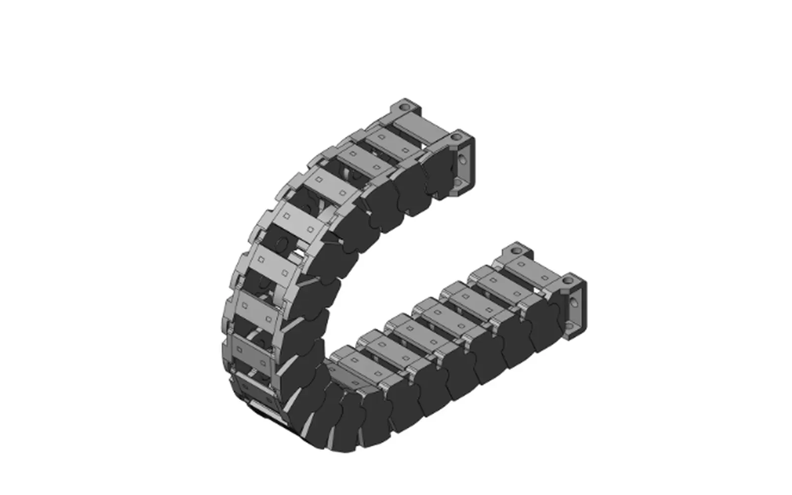
Take-out robots run short, fast strokes beside the mould, with radiant heat and release-agent mist. Five points: cable OD, radius, noise, oil, mounting.
In an injection moulding shop, the take-out robot is one of the few components that cycles thousands of times a day. It pulls the part out of the mould cavity, and every extra second it takes is a second added to the cycle. Cable carrier selection for this equipment therefore follows a different logic from routing cables along a machine tool gantry.
One boundary first: this article covers Cartesian, traverse-type and swing-arm take-out units only. A six-axis articulated robot twists at the wrist, and a two-dimensional carrier does not apply there — we covered that boundary in the article on robot arms.
A take-out robot is not a machine tool
Machine tool carriers usually run long strokes at moderate speed in a relatively clean environment. A take-out robot is the opposite:
- Short stroke, often a few hundred millimetres; traverse types run longer
- Fast cycle, tied to the moulding cycle — thousands of reversals per shift
- Mounted right next to the mould, so radiant heat and release-agent mist are unavoidable
- Installation space squeezed by the frame, safety guards and air lines, which makes the bend section hard to place
These four points set the selection order: fix the mounting position and bend radius first, then inner height and width, and only then decide whether the low-noise version is worth it. Reverse the order and you will rework the design.
Three take-out architectures, three mounting methods
Same task, but the carrier is fitted very differently depending on the structure:
| Architecture | Typical routing | Carrier form | Watch out for |
|---|---|---|---|
| Traverse type | Above the cross beam, horizontal | Flat mounting, longer stroke | Beam stiffness, chain sag |
| Swing-arm type | Arm side or frame side, swinging | Short chain, follows the arm | Bend section must clear the guard |
| Vertical / side entry | Column side, vertical lift | Vertical mounting | Self-weight sag, needs guidance |
| Six-axis articulated | Wrist rotation | 2D carrier not applicable | Requires a 3D torsion-capable design |
We build the first three as two-dimensional routing. The fourth is outside our scope, and we say so rather than force a fit.
A short stroke makes it easier to pick the radius too small
This is counter-intuitive. A short stroke suggests a short chain, so people assume any small radius will do. But the bend radius is not set by the stroke — it is set by the cable outer diameter.
Choose the radius too small and the cable is squeezed repeatedly in the bend section. Copper strand fatigue starts inside and works outward, invisible at first. By the time you see intermittent signals and servo alarms, a batch of cable is usually gone. Common industry practice is at least 5 to 7 times the outer diameter for power and control cables, and a larger multiple for encoder cables and fibre optics — always confirm against the cable maker's datasheet. This is not a number to guess.
The real constraint of a short stroke lies elsewhere: with few chain links, the bend section stays in almost the same place and is loaded repeatedly. Either move the fixed end back a little so the bend section has room to travel, or accept concentrated wear in that short section and shorten the inspection interval. The effect of speed and acceleration on link fatigue is covered in this article.
Heat and oil mist at the mould decide material and position
Mould temperature depends on the material and process and ranges from a few dozen to well over one hundred degrees Celsius. The robot only stays in the mould area briefly, but the carrier lives there permanently.
Two separate issues:
- Temperature margin. The rated operating temperature of the low-noise series is -20°C to +120°C. That is the continuous range of the material, not a short-term heat peak. Keep the mounting position away from the area directly above the cavity and from the hot-air zone beside the barrel; moving half a metre outboard is worth doing.
- Oil. Release agents and ejector-pin grease form a mist that settles on the links. Glass-fibre reinforced nylon tolerates common greases reasonably well — the problem is not dissolution but that oily residue traps dust and turns into abrasive paste that wears the pins. In shops with oil mist, link cleaning belongs in the maintenance schedule, not something you do when you hear noise.
Where a stricter cleanliness class is required — medical or optical moulding, for example — the cleanroom series is the right family. It follows different logic, with different materials and a different temperature range, and the two should not be mixed.
Safety signals run through this chain too
For the interface between the moulding machine and the take-out unit, the mainstream European practice is EUROMAP 67. It defines emergency stop, safety gate and mould-area-free signals as two-channel redundant transmission; the plug contacts must handle at least 250 V / 10 A, with signal voltages not exceeding 50 V DC or 250 V AC. The design principles of the emergency stop function itself are set out in ISO 13850; the interface is only a transmission channel and does not replace the e-stop design. That means the interface cable carries a safety circuit, not just data.
Three direct consequences:
- Safety-circuit conductors must not be bundled casually with power conductors; separators have to do real work
- No arbitrary joints in the middle of the cable; cut length to the actual route
- A broken or worn cable inside the carrier does not mean "signal lost" — it means the safety function fails
On the machinery safety side, follow the risk assessment approach of ISO 12100, set performance levels for safety-related control parts per ISO 13849-1, check the robot itself against ISO 10218-1, the moulding machine against ISO 20430, and wire the electrical equipment per IEC 60204-1. None of these standards tells you how to choose a carrier, but they do define how serious a cable failure is. That is why routing on a take-out unit cannot be done to a "as long as it conducts" standard.
The 60% fill rule: use the outer diameter
The low-noise series (model codes carry a J suffix) spans 19 inner-width steps from 25 to 125 mm. There is only one way to converge:
Sum of all cable cross-sections (including air and hydraulic hoses) ÷ (inner height × inner width) ≤ 60%
If you exceed it, step up one inner width. Where the bundle includes air or vacuum lines, size the tubing per ISO 4414 and the component supplier's data — do not infer it from cable diameters.
The usual mistake is how the area is calculated. Cable cross-section means the circular area from the outer diameter, not the nominal conductor size. A cable with a 7 mm outer diameter has a circular area of about 38 mm², while its nominal conductor may be 1.5 mm² — a factor of more than twenty. Calculate with conductor area and you will undersize the inner width by a full step, and the bundle will be crushed. The calculation for stacking layers and separator allocation is in this article on inner height.
Harnesses on take-out robots are thicker than people expect: servo power, encoder, air, vacuum, safety circuit, plus the EUROMAP interface cable — seven or eight runs is common. Make the list first, then calculate.
What the low-noise design reduces is impact, not machine noise
The dominant noise in a moulding shop comes from the hydraulic pump and the clamping unit; the carrier is a small part of it. So let us be clear: fitting a low-noise chain will not make the shop quiet.
The low-noise version does two things — it enlarges the link impact face and adds cushioned bump stops to reduce the impact energy as the chain returns, and it tightens the clearance in the friction pair to cut high-frequency chatter. What it reduces is that rattling link-on-link sound.
Why it is worth considering on a take-out robot: a fast cycle means a high impact frequency, thousands of times per shift. That short, high-frequency sound is conspicuous at night and in unmanned cells, and customers often list it as an acceptance criterion. When a customer says the robot keeps rattling, the carrier is not always the cause. Measure before you replace — it is cheaper. Agree the method too: emission sound pressure level at the workstation measured per ISO 11202, with distance, background noise and operating point all recorded, otherwise the two sides measure different numbers and never agree.
One more caveat: low noise does not mean high speed. It lowers impact energy; it does not raise the speed limit. Whether a speed is acceptable depends on stroke, acceleration, harness weight and fill rate together. This is expanded in the article on low-noise carriers.
How tall the bend section is: 2R plus chain body
The most commonly overlooked number in selection is the overall height of the bend section, roughly 2R plus the chain body thickness.
Go up one radius step and the installation space has to give way. Space above the frame of a take-out unit is usually tight — guards, air lines and the beam all compete. The right method is to measure the available height, work back to the maximum permissible radius, then check whether that radius still meets the cable's minimum bend radius. If not, change the route; do not force the radius down. The multiple between radius and cable diameter is covered in this article.
Because of the bump stops, the low-noise version has a slightly taller chain body than the standard version at the same inner height. When substituting, verify three numbers: overall height, available radius steps, and end-connector hole pattern. In most cases the frame does not need modification, but each number must be checked.
Flat, vertical or side mounting: a pitfall for each
- Flat mounting (above the beam): the chain hangs below; long strokes need support rollers or a guide trough, otherwise sagging links chew the beam
- Vertical mounting (column side): chain weight bears on the bend section; a vertical guide block is not optional
- Side mounting (arm side): the bend section sweeps an arc with the arm — check interference with guards and air lines, and verify safety distances per ISO 13857
All three share one requirement: the fixed end must sit on something rigid enough. Many take-out beams are aluminium profile, and drilling straight into the profile slot works loose over time. A transition plate saves a lot of re-torqueing later. For long-stroke gantry equipment, see the gantry article.
Five common selection mistakes
- Calculating fill rate from conductor size, undersizing the inner width, and letting cables rub against each other
- Squeezing the radius below the cable's minimum bend radius to save space — broken strands appear six months later
- Cables running loose outside the chain, tied to the beam with zip ties — effectively no carrier at all
- Safety circuit and servo power sharing one separator, multiplying both interference and failure risk
- Mounting directly above the cavity, absorbing heat and oil mist, halving service life
Of these five, number 3 is most often mistaken for "we already use a carrier". Open the guard and the cables are loose, with the chain supporting only half of them.
Matching the low-noise series to a model
Six inner-height steps, inner width chosen by fill rate:
| Series | Inner height | Inner width | Bend radii | Model codes |
|---|---|---|---|---|
| Silent 18 | 18 mm | 25–50 mm | R28 / R38 / R48 / R55 | WSL01J |
| Silent 25 | 25 mm | 25–110 mm | R55 / R75 / R100 / R125 | WSL02J / WSL02JL / WSL03J |
| Silent 30 | 30 mm | 25–110 mm | R55 / R75 / R100 / R125 | WSL04J / WSL05J |
| Silent 35 | 35 mm | 25–125 mm | R75 / R100 / R125 / R150 | WSL06J / WSL06J2 / WSL07J |
| Silent 40 | 40 mm | 50–125 mm | R75 / R100 / R150 | WSL08J / WSL09J |
| Silent 45 | 45 mm | 50–125 mm | R75 / R100 / R125 / R150 / R200 | WSL10J / WSL11J |
Most take-out robots land on the 25 and 30 steps: a modest harness, sufficient inner height, and a compact bend section. With vacuum and thick air lines in the bundle, go to 35. Full specifications are on the silent carrier series page, with detail for the two most common steps on Silent 25 and Silent 30.
If you prefer to follow a process, work through the selection guide; drawings and datasheets are in the download centre.
Seven numbers I need before quoting
- Effective take-out stroke, and where the fixed end can be mounted
- Mounting method: flat / vertical / side
- Harness list: number of runs, outer diameter of each, whether air and vacuum lines are included
- Maximum speed and acceleration
- Cycle rate — reversals per minute or per mould
- Environment: mould-area temperature, release-agent mist, dust
- Maximum bend-section height the installation space allows
With these seven, selection usually lands in one pass. Without items 3 and 7, we can only give a range, not a definite model.
If unsure, photograph the harness and send it — more accurate than a description. Production and factory audits are both in Yueqing, Zhejiang. Catalogues, drawings and a selection table can be prepared for your specific working conditions. Include the seven items when you contact us and the reply will be faster.