Cable carrier for linear modules: stroke and pitch
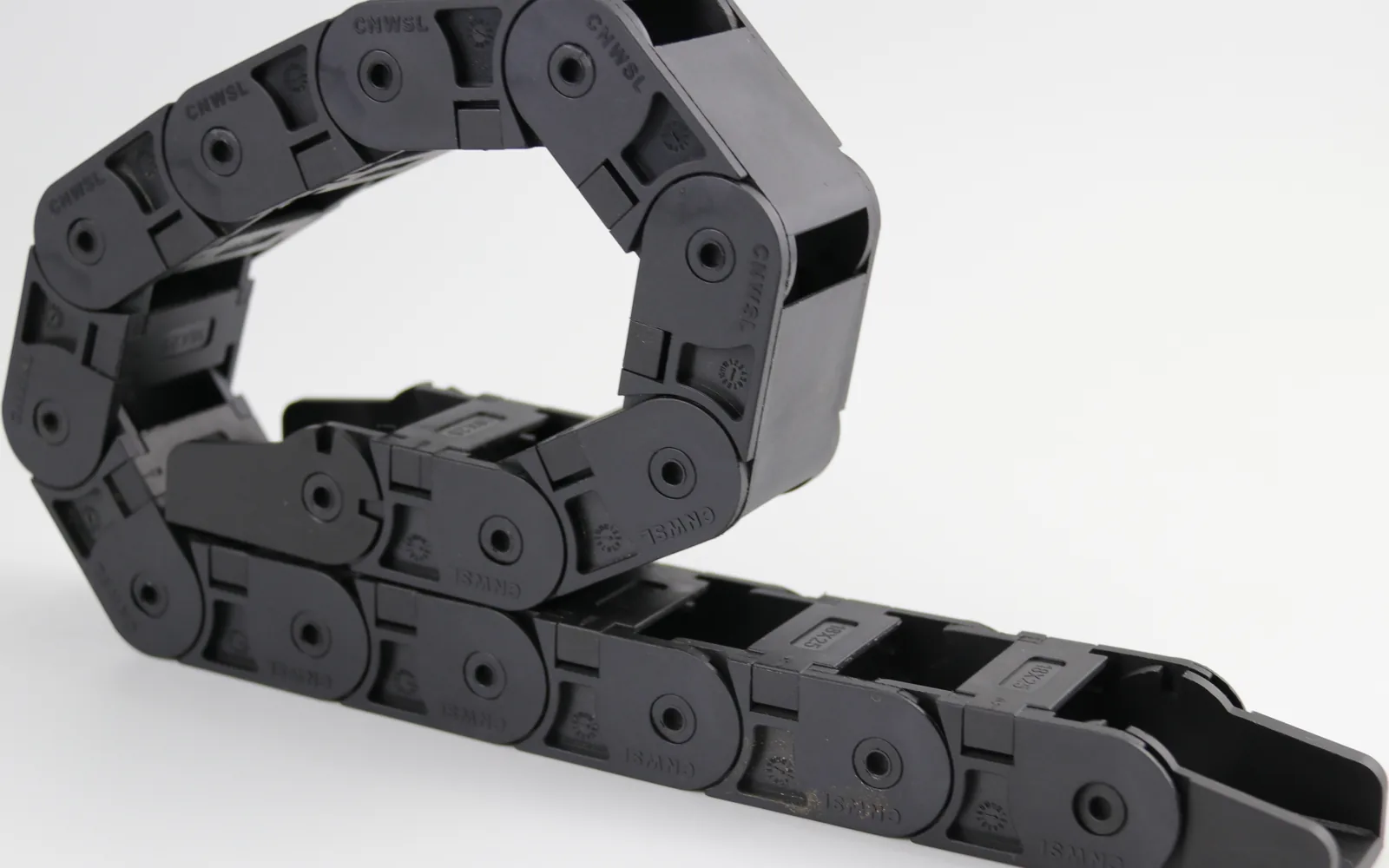
How to choose a cable carrier for a linear module: stroke, mounting height, pitch and bend radius, with the selection order and three common mistakes.
A cable carrier for a linear module is one of those cases where the duty is very clear but the selection is easy to get wrong: long stroke, high speed and tight mounting space stack up, and a single guessed parameter only shows up after the machine is assembled. This article breaks the application down and gives an order of decisions you can follow.
Why a linear module is not the same as a machine tool
Cable carriers on ordinary machine tools usually run short strokes at moderate speed, which leaves a lot of margin. Linear modules (linear stages, slide modules) are the opposite:
- Long stroke: many modules travel 1000mm or more on a single axis, sometimes 3000mm and beyond, so the carrier has to fold back on itself and follow the carriage.
- High cycle rate: on a fast line, one module can make thousands of round trips a day; pitch and hinge design decide service life.
- Tight mounting space: the module body already takes most of the room, so the carrier is often squeezed under the base or along the rail, and the bend radius is hard to enlarge.
- Real speed: many modules run above 1m/s with frequent starts and stops, which amplifies both noise and cable stress.
So the same phrase "choose a cable carrier" leads to different answers on a module and on a machine tool.
Selection order: stroke first, then height, then the model
Buyers often start by asking "which model", but the model is the last step. On a linear module the correct order is:
- Calculate the stroke: carrier length ≈ stroke / 2 + fixed-end allowance + unrolled length of the bend, worked out separately for each mounting arrangement (moving-end fixed or fixed-end fixed). Do not order from a rough estimate.
- Set the mounting height: the highest point of the running carrier must stay below any obstruction above the module (cylinder, sheet-metal guard, a second axis). If height is short, reduce the bend radius or change the routing.
- Set the bend radius: R must satisfy both the minimum bend radius allowed by the cables and the minimum R allowed by the carrier structure; take the larger of the two.
- Set pitch and opening type: look at cable count, cable diameter and how often cables are changed (frequent changes favor side-opening or fully opening).
- Only then the model: use inner height, inner width and bend radius to look up the model in the product table.
The classic consequence of reversing the order: the model arrives and does not fit, so it is forced into a smaller R, cable stress goes over the limit and cores break within two months.
Pitch: the parameter most often missed on linear modules
Pitch (link length) matters much more on a module than on a machine tool, for two reasons:
- Pitch sets how smoothly the carrier bends: at the same bend radius, a shorter pitch means a smaller angle per link, more even hinge wear and lower noise; a long pitch produces a visible "kink" at the bend, and both noise and vibration rise at speed.
- Pitch affects the unsupported span: the self-supporting length of the straight run relates to pitch. A longer, heavier pitch sags more in the middle on long strokes and needs a guide trough or additional support.
The rule is direct: the longer the stroke and the higher the speed, the more you should move toward a short pitch with a precise hinge. This is exactly why silent series exist — hinge structure and pitch design are used to bring the impact noise of fast reciprocation down.
Fill factor: do not cross 60%
The fill factor of the carrier cavity (total cable cross-section / effective cavity cross-section) should stay within 60%. The remaining space is not wasted; it is there for three things:
- Room for relative movement during the bend — cables are not clamped inside a carrier. On a bend, inner and outer paths have different lengths, so cables must be able to shift slightly. A fully packed cavity turns that into a hard pull.
- A heat path — especially when power and signal cables are bundled together.
- Spare capacity — adding one more cable during a line upgrade is routine.
Two further rules on layout: put heavy cables on the sides and light ones in the middle (reduces off-centre load), and separate power from signal cables, by layer or by cavity.
Applying bend radius on a module
On modules the bend radius is often squeezed by lack of space, but the compromise has a floor:
- The lower limit is the larger of the minimum bend radius allowed by the cables and the minimum R allowed by the carrier.
- Oil hoses, fibre optics and thin signal wires have very different allowable radii; do not calculate them all from the thickest one.
- If space is really short, change the mounting arrangement first (moving-end fixed, add a guide trough, raise the mounting face) rather than forcing a smaller R.
A radius that is too small shows no problem at first; over time it appears as cracked cable jackets, broken shields and accelerated hinge wear. Work it out at the selection stage.
Three common mounting mistakes
- Carrier mounted the wrong way round: fixed end and moving end swapped, so the bend section turns outward and shows heavy wear after a few hundred cycles.
- Unsupported bend section: the middle sags on long strokes, the carrier rubs against itself, noise rises and life drops.
- Cables tied rigidly to the carrier: clamping the cable along the whole length removes its freedom to shift and sharply increases the chance of broken cores. Clamp at both ends and leave slack in between.
What to send when requesting a quote
To get a firm quote in one pass, the enquiry should contain at least:
| Item | What to state |
|---|---|
| Stroke | Effective stroke in mm |
| Mounting | Moving-end fixed / fixed-end fixed, horizontal or not |
| Available space | Clearance height above, maximum bend radius allowed |
| Cable list | Count, outer diameter, type (power / signal / air / fibre) |
| Operating data | Speed, acceleration, cycles, ambient temperature |
| Special needs | Silent operation, cleanroom, ESD |
With this information the selection can usually be fixed in one round instead of three.
CNWSL products for linear module applications
CNWSL covers a full nylon cable carrier range from micro to heavy. For the "long stroke + fast reciprocation" duty of a linear module, the recommended line is the silent series, where hinge structure and pitch are designed to reduce reciprocation impact noise:
| Series | Inner height | Inner width | Available bend radii |
|---|---|---|---|
| Silent 18 (WSL01J) | 18mm | 25–50mm | R28 / R38 / R48 / R55 |
| Silent 25 (WSL02J, WSL02JL, WSL03J) | 25mm | 25–110mm | R55 / R75 / R100 / R125 |
| Silent 30 (WSL04J, WSL05J) | 30mm | 25–110mm | R55 / R75 / R100 / R125 |
| Silent 35 (WSL06J, WSL06J2, WSL07J) | 35mm | 25–125mm | R75 / R100 / R125 / R150 |
| Silent 40 (WSL08J, WSL09J) | 40mm | 50–125mm | R75 / R100 / R150 |
| Silent 45 (WSL10J, WSL11J) | 45mm | 50–125mm | R75 / R100 / R125 / R150 / R200 |
Material is glass-fibre reinforced nylon, rated -20°C to 120°C. For longer strokes requiring more inner height, the bridge-type range is also available (for example the 45 series, 45mm inner height, 50–300mm inner width).
Send the enquiry data above and we can return the matching model and drawings.
Related reading
- Speed and acceleration limits: cable carrier speed and acceleration
- Bend radius calculation: how to calculate cable carrier bend radius
- Full selection flow: cable carrier selection in 8 steps
For machinery safety and risk assessment methods see ISO 12100:2010; for cleanroom classification where the module runs in a clean environment see ISO 14644-1:2015. General electrical safety requirements for machines are covered by IEC 60204-1:2016.
For a selection proposal or drawings for a specific stroke, reach us via contact or get the selection documents.