Cable carrier selection: the 8-step method
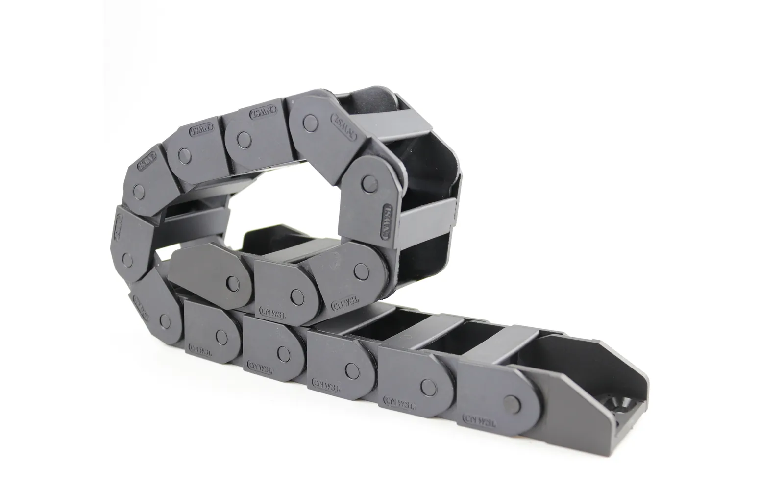
Choosing a cable carrier is not guesswork. This 8-step flow covers duty, cable list, fill factor, bend radius and material, plus size tables.
1. Get the order right: work out the duty first, pick the model last
Ask "how do I choose a cable carrier" on most shop floors and you will get handed a model table to scan for something that looks usable. The correct order is the opposite: work the duty and the cable list out first, and the model falls out of the arithmetic at the end — it is not the starting point.
Doing it backwards causes two typical failures. One: you pick the inner width from the frame width, fit the cables, and only then notice the fill factor is over — and after a while the cables chafe against each other in the bend. Two: you buy the chain first, then work out the bend radius and find R is too small, so either the cables become thinner or the whole chain is scrap.
This article splits selection into 8 steps. The first 3 are pure arithmetic, the middle 3 fix dimensions, the last 2 handle length and environment. Work through all 8 and the model is essentially unique; what remains is picking a step from the maker's listed range.
In one line: the input to carrier selection is the duty; the output is the model. Reverse the order and every later step is damage control.
2. Steps 1–3: duty, cable list, inner width
Step 1 Define the motion duty
Establish how the machine actually moves; this feeds every calculation that follows:
- Travel S: the one-way movement. Travel governs whether you need to consider a gliding arrangement or support.
- Speed and acceleration: high-speed duty calls for tighter fill-factor margin — see limits of speed and acceleration.
- Mounting arrangement: unsupported, gliding, or on rollers; and whether the load is off-centre.
- Environment: temperature, oil, coolant, dust, cleanliness class.
The output of this step is a duty sheet. Leave any line blank and the dimensions computed downstream are not trustworthy.
Step 2 Inventory the cables and hoses
List everything that has to go inside the chain, item by item — do not estimate from memory:
- each cable's outer diameter (the real OD with screen and jacket), quantity and weight per metre;
- air and hydraulic hoses, with outer diameter and count — they take cross-section just like cable;
- total cross-section and total weight of cables and hoses.
Two frequent errors: counting cables but not hoses, and using the nominal diameter instead of the actual OD. Fill factor and bend radius are both built on this list; get the list wrong and everything after it is wrong.
Step 3 Calculate inner width and fill factor
Inner width is not "as wide as the frame"; it is back-calculated from the total cable cross-section:
- keep the cross-sectional fill factor within 60% (hoses included), leaving about 40% free;
- cables should be separated by dividers so they do not ride on each other;
- group cables of very different cross-section.
Once the fill factor passes 60%, cables press on each other in the bend and their actual bend radius is smaller than the design value — designed at 10D, the cable sees 7D, and life drops sharply. The full method and a worked example are in how to choose the inner width.
3. Steps 4–6: bend radius, inner height, series and model
Step 4 Fix the bend radius R
R has to sit between two numbers:
- the floor: the cable maker's dynamic minimum bend radius, usually 7.5–10 × the outer diameter D. From 10m of travel, start at 10D and add 20% margin;
- the ceiling: the mounting height the machine can spare, taken in practice as ≈ 2R + link thickness + clearance.
Then step one size up in the carrier maker's R table; never take the smallest value that passes. For background: the German standard DIN VDE 0298-3 gives 4D–5D for drag chain operation — a floor to avoid damage, not a life recommendation. Method and worked example in how to work out the bend radius.
Step 5 Fix the inner height
Inner height is set by two things; take the larger:
- the height of the cable bundle — the thickest cable's outer diameter plus the number of groups;
- whether connectors, terminals and elbows fit — a connector is usually bulkier than the cable, and this is the most commonly missed item.
Too little inner height and the connector will not go in, the cables are pinched vertically, and the chain is pushed apart in running.
Step 6 Select the series and the specific model
With inner width and inner height fixed, match them in the series table (see the quick-reference in section 5). If nothing matches exactly, step up rather than down.
Several series often share an inner height; they differ in construction and in how many R steps they offer. This is the first point at which a "model" appears at all.
4. Steps 7–8: length and mounting, material and environment
Step 7 Fix the length and the mounting arrangement
Chain length is not "as long as the machine runs". The usual estimate is
Lk ≈ S / 2 + π × R
where S is the travel. For S = 2000mm and R = 100mm, the bend arc is π × 100 ≈ 314mm, so the chain is about 1314mm, plus the maker's safety margin. This is an estimate; for the order, use the maker's travel-to-length table.
Confirm the arrangement at the same time: for long travel — from about 10m in engineering practice — consider a gliding arrangement or support rollers, so the chain is not left unsupported over a long span.
Step 8 Fix the material and environment
The environment dictates the material, and this step is often skipped entirely:
- normal duty: glass-fibre reinforced nylon, continuous working temperature −20℃ to 120℃;
- cleanroom duty: material becomes TPU, again −20℃ to 120℃, with particle emission and the cleanliness class confirmed to ISO 14644-1:2015;
- hot, oily or swarf-heavy duty: assess separately; material comparison in how to choose the material.
If the whole machine has to meet electrical compliance, bring in the conductor routing and bending requirements of IEC 60204-1:2016 (safety of machinery — electrical equipment of machines). If the machine needs a safety assessment, the duty definition should also follow the risk assessment method of ISO 12100:2010. Both operate at machine level and are a separate layer from sizing the carrier itself; neither replaces the other.
5. CNWSL series inner height and width quick reference
Nylon bridge-type series (glass-fibre reinforced nylon, −20℃ to 120℃):
| Series | Inner height | Inner width |
|---|---|---|
| Series 5 | 5mm | 5–7mm |
| Series 6 | 6mm | 10mm |
| Series 7 | 7mm | 7–10mm |
| Series 10 | 10mm | 6–40mm |
| Series 15 | 15mm | 15–50mm |
| Series 18 | 18mm | 18–50mm |
| Series 20 | 20mm | 25–103mm |
| Series 25 | 25mm | 25–103mm |
| Series 30 | 30mm | 25–103mm |
| Series 45 | 45mm | 50–300mm |
| Series 65 | 65mm | 50–300mm |
| Series 80 | 80mm | 100mm |
→ Full specifications: micro series, medium series, heavy series.
Silent series (glass-fibre reinforced nylon, −20℃ to 120℃):
| Series | Inner height | Inner width |
|---|---|---|
| Silent 18 | 18mm | 25–50mm |
| Silent 25 | 25mm | 25–110mm |
| Silent 30 | 30mm | 25–110mm |
| Silent 35 | 35mm | 25–125mm |
| Silent 40 | 40mm | 50–125mm |
| Silent 45 | 45mm | 50–125mm |
→ Low-noise selection: how to cut carrier noise.
Cleanroom WWC series (TPU, −20℃ to 120℃):
| Series | Inner height | Inner width | Available bend radius R |
|---|---|---|---|
| WWC15 | 15mm | 25mm | R40 / R50 / R60 / R70 |
| WWC18 | 18mm | 32mm | R40 / R50 / R60 / R70 |
| WWC22 | 22mm | 40mm | R40 / R50 / R60 / R70 |
| WWC28 | 28mm | 65mm | R40 / R60 / R70 / R90 |
| WWC35 | 35mm | 65mm | R60 / R70 / R90 |
→ Cleanroom selection is covered separately in the cleanroom carrier selection guide and the cleanroom series.
6. Five hard limits that cannot be traded
Some parameters in the 8 steps are negotiable. These five are not:
- Fill factor ≤ 60% (hoses included). Exceeding it trades cable life for inner width, and the space saved is not worth it.
- R ≥ the cable's dynamic minimum bend radius. This is the cable maker's hard requirement; R cannot go lower.
- Mounting height ≥ ≈ 2R. The most commonly missed and the most costly: if the frame has not left the room, the routing has to be redesigned.
- Inner height must pass the connectors. If terminals and elbows will not fit, an accurate inner height is useless.
- Material must match the environment. Cleanroom uses TPU cleanroom series; a standard nylon series cannot be substituted directly — the particle emission behaviour and the compliance logic are not the same.
7. Put the 8 steps into the enquiry
To get the right solution first time, give the maker at least this:
- Duty: travel, speed, acceleration, arrangement (unsupported / gliding / supported);
- Cable list: outer diameter, quantity, weight per metre, hoses included, actual OD with screen;
- Available mounting height (the most commonly omitted and the most critical);
- Environment: temperature, oil, cleanliness class;
- Electrical compliance requirements (state it if the machine must meet IEC 60204-1 type requirements).
Selection criteria and form templates are in the selection guide; catalogues and drawings under downloads. Send the parameters above and we can produce a solution with inner width, inner height, R and length all fixed — contact us.
One boundary worth stating: our production site is in Yueqing, Zhejiang (Tiancheng Street), where factory audits can be arranged; Changzhou is a sales office, not a factory. On quality systems, IATF 16949 is held; ISO 14001 is currently to be confirmed — automotive customers needing both certificates should check with us before quotation.
8. Summary
- Order: work out duty and cables first, then dimensions; the model falls out last.
- First 3 steps: duty sheet → cable list → inner width and fill factor (≤60%).
- Middle 3 steps: R (7.5–10D, step up one size) → inner height (must pass connectors) → series and model (step up if nothing matches).
- Last 2 steps: length ≈ S/2 + πR, consider gliding for long travel; material by environment (TPU for cleanroom).
- Five limits: fill factor, R, mounting height, connectors through the inner height, material matching the environment.