Antistatic cable carriers: ESD selection rules
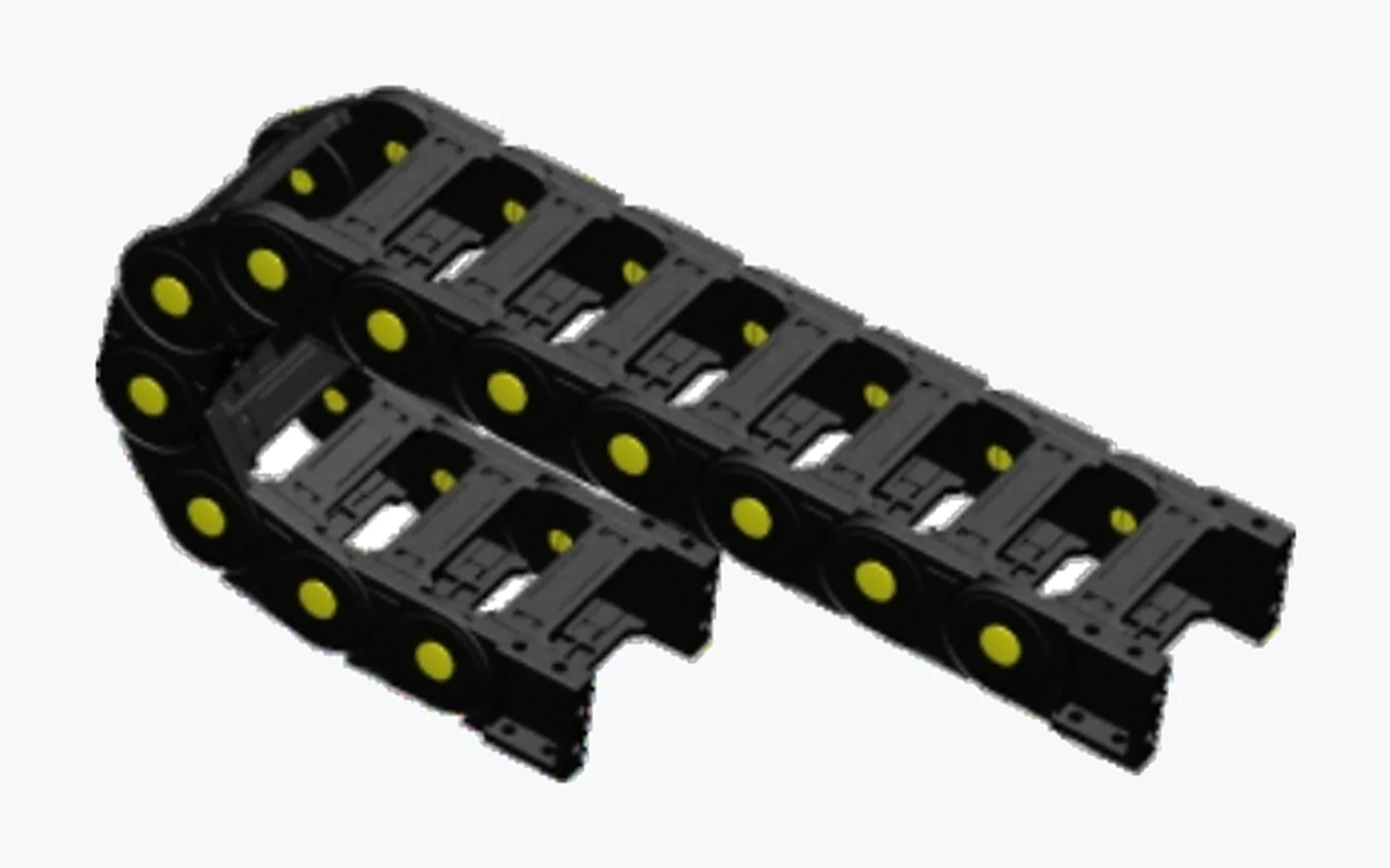
Cleanroom class counts particles, ESD counts charge. How to choose a resistance band, why black proves nothing, and why grounding fails.
Cleanliness and ESD are two different things
A cleanroom acceptance test counts particles. ISO 14644-1 classifies air cleanliness from ISO Class 1 to 9 by particle concentration per unit volume, counting the 0.1 to 5 micrometre range, as set out in ISO 14644-1:2015. Whether a piece of equipment belongs in a cleanroom is assessed under ISO 14644-14:2026, and that standard explicitly excludes "physical properties of materials (e.g. electrostatic, thermal properties)" from its scope. The standards themselves keep the two subjects apart.
ESD looks at something else entirely: what order of magnitude the surface resistance sits in, whether charge has a path to leave, and how fast it leaves.
The two topics meet on the machine, but they are not the same test. A cable carrier can pass every particle count in a cleanroom qualification and still be a perfectly good insulator. Run it back and forth for an hour and the links rubbing against the cable jackets will charge it to several kilovolts. The problem only shows up when it discharges into a wafer or an assembled PCB, or when the charged chain attracts particles onto the work surface. Then someone pulls the particle emission report, and the report is fine, because that report never measured resistance.
So cleanliness and ESD need separate specifications and separate evidence. One report cannot cover two requirements.
The charging source is the chain itself
In an ESD context a cable carrier is a generator that never stops running. Every stroke puts at least three friction pairs to work: link against link at the hinge, cable jacket against the inner cavity, link against separator. Each touch-and-separate cycle is a charge separation event.
Ordinary engineering plastics sit in the 10¹⁴ to 10¹⁶ Ω range for surface resistance. Charge has nowhere to go, so it accumulates. Once it builds up, there are two outcomes. Either it discharges into a nearby conductor and damages a device through HBM or CDM failure, or the charged body attracts airborne particles and the workpiece fails its particle count. That second path ties ESD and cleanliness directly together.
IEC 61340-5-1:2024 addresses devices with withstand voltages of 100 V or more (human body model) and 200 V or more (charged device model), and requires the voltage on isolated conductors to be held below 35 V. That 35 V limit is exactly the "do not let a floating conductor build up voltage" rule. A conductive carrier that is not bonded to ground is precisely such an isolated conductor.
Surface cleanliness has its own method: ISO 14644-9:2022 assesses it by particle concentration per unit area, covering 0.05 to 500 micrometres, and it does not deal with charge either. Two standards, two halves, and the causal link between them is yours to make.
Surface resistance comes in three bands
The industry bands, consistent between the IEC 61340 series and ANSI/ESD S20.20:
| Band | Surface resistance | Charge behaviour |
|---|---|---|
| Conductive | < 1×10⁴ Ω | Very fast bleed, near short circuit on contact |
| Dissipative | 1×10⁴ ~ < 1×10¹¹ Ω | Controlled bleed, neither fast nor stuck |
| Insulative | ≥ 1×10¹¹ Ω | Charge cannot leave, keeps accumulating |
The instinct is "more conductive is better". It is not. For sensitive devices, a conductive surface discharges too fast, dumping energy into the part in a very short time, which is harder on CDM-sensitive structures. Conductive plastics also get there by loading fillers, and a high filler ratio costs impact strength and wear resistance. The dissipative band is the useful one: charge has a path, but it takes its time.
Which band you need is set by the customer's ESD control plan, not by the supplier's preference. Front-end semiconductor, panel, and pharmaceutical operations all set different limits, and within one plant different workstations may differ. Put this into the technical agreement up front; it is cheaper than arguing about responsibility later.
"Black" is not evidence
This is the most common misjudgement in the category. Carbon black serves two purposes in plastics: conductive filler, and black colorant. The same black chain may be a dissipative material, or it may simply be dyed, with resistance still up around 10¹⁵ Ω.
Only data settles it, and the data has to be specific: which standard, which test method, how many measurement points, what the average is, and at what temperature and humidity it was measured. Miss one item and the number means little.
Humidity is the item most often skipped. Plenty of parts advertised as antistatic measure nicely at 50% RH and turn back into insulators in a 12% RH dry room, because their conductive path is a film of adsorbed water. This is why IEC 61340-5-1 requires certain ESD protective items to be verified under low-humidity conditions. A dry cleanroom is exactly where this trap springs.
Measuring resistance is itself a standardized job. IEC 61340-2-3:2016 specifies test methods for resistance and resistivity of solid materials, covering 10 kΩ to 1 TΩ, and separates instrumentation for laboratory evaluation, acceptance testing and periodic verification. A multimeter waved at a sample is not data.
Test data from our WWC samples
For our own product, here are the numbers. A WWC cleanroom carrier body sample was submitted to Centre Testing International (CTI, Guangzhou), tested for volume and surface resistance per ANSI/ESD S20.20:2021 under report A2260607033101E, issued 28 July 2026, seven pages.
| Item | Average of six points | Test conditions |
|---|---|---|
| Volume resistance | 1.19×10⁶ Ω | 23±2℃ / 12±3% RH |
| Surface resistance | 2.42×10⁶ Ω | 23±2℃ / 12±3% RH |
Three condition details are worth recording: the sample was preconditioned for 48 hours at 23±2℃ and 12±3% RH and tested in that same environment; test voltage was 100 VDC applied for 15 seconds; the equipment was a TREK 152-1 impedance tester with an FHA328D dry cabinet. The six surface resistance readings ranged from 1.98×10⁶ to 2.86×10⁶ Ω, a reasonably tight spread.
Both figures sit in the middle of the dissipative band, roughly five orders of magnitude below the 10¹¹ Ω insulative boundary. That margin matters: it has to absorb contamination, ageing and batch variation.
The limits of the evidence matter too. This is a commissioned test: the result applies to the submitted sample only, and it does not mean a machine or a production line has passed ESD certification. The report itself notes the data is intended for research, teaching, internal quality control and product development. A customer who needs it for a system audit must still run machine-level testing under their own ESD control plan. Note also that the WWC body is TPU, rated -20℃ to 120℃; outside that window the material ages and resistance drifts.
A compliant chain is not a grounded chain
Compliant material is only the first step. What the chain actually does on the machine depends on three more things.
First, the joints. A carrier is built from discrete links, and every joint inserts a contact resistance in series. The ESD Association published an evaluation of 33 grounding chains in January 2024 (Drag Chain Evaluation), and its central finding was that link-to-link contact resistance dominates the total, not the contact between chain and floor as usually assumed; dirt and corrosion push contact resistance up, and coated chains are effectively insulators. That study looked at metal grounding chains for mobile workstations, so its numbers do not transfer directly to plastic carriers, but the mechanism does: the more contact points in series, the less predictable the chain.
Second, the grounding path. There are two common approaches: conduct through the body material all the way to the machine ground, or keep the body dissipative and run a separate ground wire to the machine's equipotential point. The first is simpler but depends on every hinge staying conductive. The second adds a step and is easier to measure and trust. Where conductive parts join the machine's earthing system, IEC 60204-1:2016 sets additional protective bonding requirements that cannot be bypassed.
Third, contamination. Coolant mist, dust, cleaning agent residue, grease: any of them on a link changes resistance. Cleanrooms forbid grease anyway, so that one is comparatively easy to control. Machining shops are the opposite and are the main source of field failures.
So acceptance should measure two numbers: end-to-end resistance of the chain, and resistance from chain body to the machine ground point. Measure once after installation, and again after cleaning and maintenance. The second measurement is usually the one that exposes the problem.
The two measurements are not the same kind of test. The first is close to product acceptance; the second is in-service compliance verification. IEC TS 61340-5-4:2026 covers verification of ESD control items already in use and explicitly excludes product qualification. One cannot substitute for the other.
Three requirements that fight each other
Antistatic performance is not just a filler additive; it usually conflicts with two other requirements.
- Antistatic versus particle emission: conductive fillers can themselves be a source of particle shedding. A formulation with carbon black or metal powder needs its cleanliness data redone; the original cleanroom report does not carry over.
- Antistatic versus mechanics: fillers reduce toughness and wear resistance. At the same wall thickness, impact life gets shorter, which matters most in heavy-duty duty cycles.
- Antistatic versus temperature: TPU's -20℃ to 120℃ is the edge of the normal range. Running continuously near that edge ages the material and shifts resistance.
You cannot optimize all three. Rank them by application: front-end equipment puts cleanliness first, assembly stations put ESD first, and heavy long-travel axes have to protect mechanics. Once the priority is set, the selection has an answer.
Seven questions to settle before ordering
| Item | Question to ask | Criterion |
|---|---|---|
| Resistance band | Conductive or dissipative? What target range? | Per the customer's ESD control plan |
| Test standard | Which standard, which method? | Datasheet must name standard and method |
| Test humidity | At what RH was it measured? | Dry environments need low-humidity data |
| End-to-end resistance | Value for the assembled chain? | Measure after installation, not a single point |
| Grounding method | Body conduction or separate wire? | A separate path is easier to verify |
| Material and temperature | Which material? What operating temperature? | TPU typically -20℃ to 120℃ |
| Report and batch | Third-party report? Per batch? | Report number verifiable, limits comparable |
Four traps that come up constantly
- Treating cleanroom class as ESD compliance. Passing the particle count says nothing about resistance; they are different tests.
- Judging by colour. Black does not mean conductive; ask for the resistance data.
- Testing one point instead of the whole chain. A sample at 10⁶ Ω can become 10⁹ Ω in a three-metre assembled chain, and the difference lives in the joints.
- Installing without bonding, or relying on metal pins for ground. Grease and oxide break the path, and you cannot see it.
Next step
If a project is stuck at "clean enough, but ESD fails", or the reverse, send the operating conditions: cleanliness class, device withstand voltage (HBM / CDM), stroke and speed, cable specification, ambient temperature and humidity. With those, the resistance band and the structural concept can usually be fixed.
- Material trade-offs: Cable carrier materials: PA66, TPU, steel compared
- From conditions to model number: How to choose a cable carrier in 8 steps
- The cleanliness side in depth: Cleanroom cable carrier selection guide
- Front-end semiconductor: Cable carriers for semiconductor equipment
- WWC series specifications: Cleanroom cable carriers WWC
- Download the report: ANSI/ESD S20.20:2021 antistatic test report (PDF, 7 pages)
- Quotes and samples: Contact us